
Understanding MIL-S-901E Shock Qualification for Electronic Enclosures
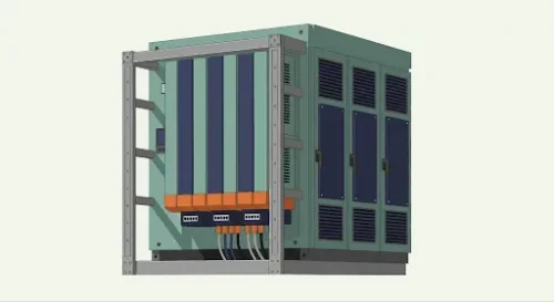 Electronic enclosures on Navy surface ships and submarines operate in one of the most mechanically demanding environments in engineering. Shock loads from weapons, near-miss underwater explosions, and sustained operational stress can destroy equipment that was never designed to survive them. MIL-S-901E — formally MIL-DTL-901E — exists to define exactly what survival means and how to verify it.
This article breaks down the standard’s structure, what changed from 901D to 901E, how test classifications affect design decisions, and where enclosure programs most commonly fail qualification.
What Is MIL-S-901E?
MIL-S-901E specifies shock testing requirements for equipment installed aboard U.S. Navy surface ships and submarines. Its scope covers the test methods, equipment classifications, pass/fail criteria, and documentation requirements that determine whether a piece of equipment — including its enclosure, mounting hardware, and isolation system — is acceptable for use in a shipboard application.
The standard does not specify how to design an enclosure. It specifies what the enclosure must survive. That distinction matters: compliance is a design outcome, not a checklist item, and the decisions that determine whether a rack passes or fails qualification begin at the concept stage.
The Transition From MIL-S-901D to MIL-S-901E
MIL-S-901D was established in 1989 and governed shipboard shock testing for nearly three decades. MIL-DTL-901E superseded it in 2017. For engineers who learned the standard on 901D, the key differences are:
| Area | MIL-S-901D | MIL-DTL-901E |
|---|---|---|
| Deck-mounted equipment test | No standardized method | Deck Simulating Shock Machine (DSSM) formally defined |
| Grade A operational requirement | Functional after test | Operable during and after test – a higher bar |
| Class definitions | Less specific on isolation provisions | Class I (no isolation), Class II (isolation permitted), Class III (must pass both) clearly defined |
| Documentation | General requirements | Explicit traceability, test report format, and configuration control requirements |
| Scope of items covered | Broad | Refined with clearer capability criteria |
The DSSM addition is the most significant change for deck-mounted electronic enclosures. Under 901D, deck-mounted equipment was often tested on the Lightweight Shock Machine (LWSM) or Medium Weight Shock Machine (MWSM) by convention. The DSSM was developed specifically to simulate the shock environment experienced by equipment mounted to a ship’s deck — a different input profile than hull-mounted equipment — and its formal inclusion in 901E means program offices now specify it by name. If your enclosure is deck-mounted and you are qualifying to 901E, confirm whether DSSM applies before selecting your test approach.
The Grade A operational requirement change is equally important. Under 901D, “functional after test” was the accepted interpretation for most programs. Under 901E, Grade A items must be operable — meaning the equipment must continue to perform its function during and after the shock event, not just survive it structurally. This has direct implications for how the enclosure and its contents are designed, particularly for shock attenuation of internal components.
Shock Test Classifications
There are four main tests of test methods under MIL-S-901E:

Lightweight (LWSM)
Used for equipment weighing up to 550 lbs. The LWSM uses a drop hammer at specified heights to deliver transient mechanical shocks. Test parameters include hammer weight, drop height, and number of blows. This is the most common test method for electronic enclosures in the light-to-medium duty range.

Medium weight (MWSM)
Used for hull-mounted equipment between 550 lbs and approximately 7,700 lbs. Heavier hammers deliver larger shock forces representative of hull-transmitted shock energy.

Deck simulating shock machine (DSSM)
A medium-weight test developed specifically for deck-mounted equipment. The DSSM uses a drop mechanism to generate a shock profile that more accurately represents the vertical and horizontal inputs experienced at deck level. Formally introduced in 901E. Frequency range is typically 4 to 10 Hz at defined G levels.

Floating shock platform (barge test)
The heavyweight test, used for equipment exceeding MWSM limits or for items that cannot be adequately tested on a machine. Underwater explosives at specified standoff distances and depths generate shock waves that propagate through the platform and into the test article — the highest-fidelity simulation of an actual underwater explosion event.
Grade & Class – Design Implications
Grade A vs. Grade B
Grade A designates equipment essential to the ship’s safety or combat capability. Grade A items must remain operable during and after the shock event. This is the classification that applies to most electronic enclosures housing communications, navigation, combat systems, or propulsion control equipment.
Grade B designates non-essential equipment. Grade B items must not become a hazard after the shock event — they cannot shed parts, tip over, or create shrapnel — but they are not required to remain functional.
Misclassifying a Grade A item as Grade B is one of the most consequential errors in the qualification process. It typically surfaces during program review when the procuring activity challenges the classification, requiring retesting under the correct criteria and potentially requiring enclosure redesign if the original design was not built to Grade A standards.
Class I, II, and III
Class I items must pass shock testing without any isolation devices. The enclosure structure itself must absorb and survive the shock input.
Class II items may use shock isolation hardware — mounts, isolators, or isolation assemblies — to attenuate the shock energy before it reaches the enclosure and its contents. Most medium and heavy-duty electronic enclosures for shipboard applications are Class II.
Class III items must satisfy both Class I and Class II requirements. This is a more demanding classification applied where isolation system failure must not result in equipment loss.
For Class II equipment, isolator selection is a primary design variable, not an afterthought.
Isolator Selection and Integration
For Class II enclosures, the isolation system determines whether the rack passes or fails. The isolator selection process involves three variables that must be balanced against each other: natural frequency, transmissibility ratio, and payload weight.
 Natural frequency is the frequency at which the isolated system resonates. For DSSM applications, the target natural frequency is typically 4 to 10 Hz — within the frequency content of the test input. An isolator selected outside this range will either amplify the shock input (if too stiff) or allow excessive displacement (if too soft).
 Transmissibility ratio defines how much of the input shock force reaches the enclosure after attenuation. A transmissibility ratio of 2.5:1 or less is a common program requirement, meaning the isolator must reduce the shock force to no more than 2.5 times the input at the enclosure mounting interface. This ratio is verified by analysis and confirmed during testing.
 Payload weight directly affects isolator sizing. Isolators are rated for a specific load range, and operating outside that range — particularly underloading, which is common when racks are specified before the final equipment complement is confirmed — changes the natural frequency and can invalidate the isolation analysis.
Two primary isolator types are used in shipboard enclosure applications. Elastomeric mounts use rubber or polymer elements that deflect under load to absorb shock energy. They are simpler, less expensive, and adequate for many applications. Wire rope isolators use coiled stainless steel cables in a defined geometry to provide isolation — they are more robust in harsh environments, more tolerant of overload, and better suited for applications where temperature extremes or chemical exposure would degrade an elastomeric element. Wire rope isolators are common in naval applications for this reason.
Isolation systems must be tested to the same standard as the enclosure. An isolator that has not been qualified to MIL-S-901E cannot be used to support a 901E qualification claim.
Common Compliance Failures
Grade misclassification. Grade A items designated as Grade B during early program phases are often not caught until the procuring activity reviews the test plan. By that point, the enclosure may have been designed to lower structural standards than Grade A requires, necessitating redesign and retesting.
Incomplete operational verification post-test. Grade A requires the equipment to be operable after the shock event, but test programs sometimes verify only structural integrity — no cracked welds, no failed fasteners — without confirming that the electronics housed in the enclosure are still functioning. The full operational check must be part of the test procedure.
Untested payload configuration. Shock testing must be performed with a representative payload installed. Testing an empty rack or a rack with ballast weights that do not match the actual equipment mass distribution produces results that may not be valid for the as-deployed configuration. If the payload is not finalized at the time of testing, work with the procuring activity to define a worst-case configuration.
Isolation hardware not qualified to the same standard. Using commercially sourced isolation mounts without confirming their qualification to MIL-S-901E is a common shortcut that can invalidate test results. Isolation hardware must be traceable to a 901E-compliant qualification.
Natural frequency outside the test input range. An isolation system designed for a natural frequency outside the DSSM input range (4–10 Hz) will not perform as intended during testing. This is most often a consequence of late-stage isolator selection after the enclosure geometry and payload are already fixed.
Design Checklist – 901E Compliance
Before entering qualification testing, confirm the following:
- Equipment grade (A or B) confirmed with the procuring activity and documented
- Equipment class (I, II, or III) confirmed and isolation system selected accordingly
- Test method (LWSM, MWSM, DSSM, or barge) confirmed based on weight and mounting configuration
- Isolation system sized to target natural frequency within program requirements
- Transmissibility ratio analysis complete and compliant
- Isolation hardware traceable to MIL-S-901E qualification
- Representative payload configuration defined and documented
- Operational verification procedure defined for post-test assessment
- Enclosure structural design reviewed for shock load paths — frame geometry, mount point locations, fastener specification
Choose A&J Manufacturing for Shock- and Impact-Resistant Electronic Enclosures
A&J has designed and manufactured shipboard electronic enclosures to MIL-S-901E requirements for programs across the U.S. Navy fleet. Our enclosures are built to Grade A, Class II standards using aluminum alloy 6061-T6 construction with isolation systems sized and analyzed for the specific program payload and frequency requirements.
If you are in the early design stages of a shipboard enclosure program — or evaluating whether an existing design will survive qualification — two resources can help.
Score your enclosure’s spec readiness. Our interactive assessment evaluates your design across five compliance dimensions — structural, environmental, shock, EMI/EMC, and thermal — and delivers a gap analysis with your score. [Take the assessment →]
Talk to an A&J engineer. If you already know where the gaps are and want to discuss design options, our engineering team can review your requirements and identify compliance risks before they reach the test floor. [Contact us] or [download our Design Requirements Worksheet] to get started.