Posted by Courtney Pardal on | Comments Off on Mitigating EMI/RFI Interference in Rack Enclosures for Defense and Aerospace Applications
Electromagnetic interference (EMI) and radio-frequency interference (RFI) pose critical challenges in defense and aerospace applications. Mission-critical electronics must operate reliably in high-noise environments, where even minor disruptions can compromise system performance and safety. Engineers working with rack enclosures must implement robust shielding, grounding, and filtering strategies to mitigate interference and ensure compliance with MIL-STD-461, DO-160, and other stringent standards. This article explores best practices for reducing EMI/RFI in rack-mounted systems.
1. Shielding Strategies for Rack Enclosures
Effective EMI shielding begins with the enclosure itself, as inadequate shielding can lead to excessive radiated emissions and system malfunctions. Selecting the right materials and design features can significantly reduce interference:
Conductive Materials: Enclosures made of aluminum, specifically Aluminum 6061-T6 and Alloy 6063-T5, provide effective attenuation of EMI due to their excellent electrical conductivity and lightweight properties. These alloys offer high shielding effectiveness by reflecting and absorbing electromagnetic waves, preventing emissions from escaping or external interference from penetrating the enclosure. Additionally, their natural oxide layer provides corrosion resistance, ensuring long-term reliability in demanding aerospace and defense environments.
Conductive Gaskets and Seals: EMI-shielded enclosures should include conductive elastomer gaskets at panel joints, doors, and access points to prevent leakage.
Honeycomb Vent Panels: Shielded ventilation panels maintain airflow while blocking high-frequency emissions. These panels are available in various cell sizes and angles, such as 30-degree and 45-degree configurations, to optimize shielding effectiveness while ensuring adequate ventilation. The choice of angle impacts both airflow resistance and attenuation, allowing engineers to balance thermal management with EMI mitigation.
Transparent EMI-Shielded Windows: When displays or observation ports are required, laminated conductive films or fine-mesh shielding can be used to maintain protection.
2. Grounding and Bonding Techniques
A well-designed grounding and bonding strategy minimizes unwanted signal coupling and ensures enclosure effectiveness by providing a controlled path for electrical currents to dissipate safely. Properly implemented grounding techniques help stabilize voltage levels, reduce differential-mode interference, and enhance overall electromagnetic compatibility (EMC) within the enclosure.
Single-Point Grounding: Establishing a single, well-defined ground reference prevents circulating ground loops that can exacerbate EMI.
Low-Impedance Connections: Using braided ground straps and minimizing ground path resistance reduces differential mode noise.
Chassis Bonding: Ensuring all components, including doors and panels, maintain a continuous conductive path prevents unintended radiated emissions.
3. Cable and Connector Management
Poorly routed cables and improper connector selection can introduce significant EMI/RFI issues. For example, running unshielded signal cables in close proximity to high-power lines can induce unwanted noise, leading to degraded signal integrity or even system malfunctions. Similarly, using non-filtered connectors in high-frequency environments can allow electromagnetic interference to propagate, affecting overall system performance.
Shielded Cables: Using twisted-pair shielded cables for power and signal lines helps mitigate conducted emissions.
Filtered Connectors: EMI-filtered connectors, such as MIL-DTL-38999 or custom multi-pin solutions, integrate capacitive and ferrite filtering to suppress high-frequency noise.
Proper Cable Routing: Maintaining separation between power and signal lines, avoiding loops, and securing cables with conductive clamps can reduce unwanted emissions.
4. Noise Suppression
Noise suppression within the rack is critical to maintaining system integrity and minimizing interference between components. Implementing the following strategies can significantly enhance noise mitigation:
Conductive Rack Coatings: Using conductive paint or plating on rack interiors helps reduce radiated emissions by providing additional shielding.
Damping Materials: Applying EMI-absorbing foam or ferrite-loaded materials within enclosures can suppress high-frequency emissions inside the rack.
Vibration Isolation Mounts: Mechanical vibrations can generate microphonic noise that affects sensitive electronics; using isolation mounts can help mitigate this issue.
Rack Grounding Techniques: Ensuring racks are properly bonded to facility ground reduces stray currents and minimizes EMI coupling between mounted equipment.
5. Compliance Testing and Validation
Ensuring rack enclosures meet stringent EMI/RFI requirements necessitates thorough testing and validation. MIL-STD-461 defines the electromagnetic compatibility (EMC) requirements for military equipment, covering conducted and radiated emissions as well as susceptibility. It includes specific test procedures such as conducted emissions (CE), radiated emissions (RE), conducted susceptibility (CS), and radiated susceptibility (RS) to ensure electronic systems can operate without interference.
A common failure occurs when enclosures do not provide adequate shielding at panel seams, resulting in radiated emissions exceeding MIL-STD-461 limits. Another frequent issue is improper grounding of the enclosure, which can create ground loops that introduce unwanted noise and degrade system performance. Additionally, inadequate cable shielding and termination can allow high-frequency emissions to escape, causing interference with nearby systems.
These failures can lead to system malfunctions in mission-critical environments and signal degradation, requiring costly redesigns and retesting to achieve compliance.
Conclusion
EMI/RFI mitigation in defense and aerospace rack enclosures requires a multifaceted approach, integrating shielding, grounding, cable management, power filtering, and rigorous compliance testing. By implementing these best practices—such as selecting proper shielding materials, ensuring effective grounding, managing cables and connectors, filtering power lines, and adhering to MIL-STD-461 compliance—engineers can enhance the resilience of mission-critical systems. These measures help ensure robust operation in the harshest electromagnetic environments, reducing the risk of interference-related failures.
For those designing next-generation enclosures, considering EMI mitigation early in the design process reduces costly redesigns and certification failures. Are there specific EMI challenges you’ve encountered in rack enclosures? Share your insights in the comments below.
The mission doesn’t stop—and neither should your insight. Subscribe to Rack and Ready for monthly strategies on enclosure design, MIL-STD compliance, cooling, and integration in defense systems.
Posted by Courtney Pardal on | Comments Off on Integrating Rack Consoles: Enhancing Your Rack Enclosure’s Usability
In today’s fast-paced technological landscape, the efficiency and usability of your equipment are paramount, especially in environments that demand high reliability and quick access to systems. In this post, we will explore how integrating rack consoles can optimize your rack enclosures for better performance and user experience.
What Are Rack Consoles?
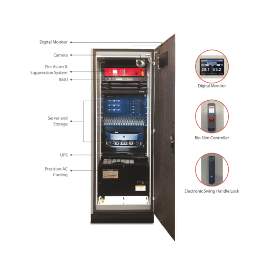
Rack consoles are essential components that allow users to interface with rack-mounted equipment easily. Typically housed in a rack enclosure, these consoles can include various input devices, such as keyboards, touchscreens, and monitors. By consolidating control and access to multiple devices in one location, rack consoles streamline operations and improve workflow.
Benefits of Incorporating Rack Consoles
Incorporating rack consoles into your setup can significantly enhance the management and operation of your electronic equipment. Here are the key benefits and considerations to keep in mind:
1. Centralized Control
Streamlined Management: Rack consoles integrate multiple control interfaces—such as keyboard, monitor, and mouse—into a single unit, allowing operators to manage multiple servers or devices from one location.
Efficient Monitoring: Provides a consolidated view of your equipment, making it easier to monitor performance and troubleshoot issues.
2. Space Optimization
Rack-Mounted Solution: By housing the keyboard, monitor, and mouse in a single, rack-mounted unit, you save valuable floor and desk space. This is particularly beneficial in data centers or server rooms where space is at a premium.
Organized Environment: Reduces clutter and keeps control equipment neatly contained within the rack, contributing to a more organized workspace.
3. Enhanced Accessibility
Easy Access: Rack consoles allow for quick and easy access to the control interface of your equipment. This is especially useful for performing maintenance tasks or making configuration changes.
Retractable Design: Some rack console designs feature a retractable or sliding design, which means you can pull out the console when needed and push it back in to save space.
4. Improved Ergonomics
Adjustable Positions: Consoles can be designed with adjustable or ergonomic features that enhance user comfort during prolonged use. For instance, some models offer adjustable screen angles and keyboard heights.
Reduced Physical Strain: Consolidating control functions into one unit minimizes the need to move between different devices, reducing physical strain on the operator.
5. Increased Security
Lockable Designs: Many rack consoles come with lockable doors or drawers, which can enhance security by restricting access to sensitive control interfaces.
Reduced Risk of Unauthorized Access: By integrating control interfaces into a rack-mounted solution, you can better secure access to the equipment and reduce the risk of unauthorized tampering.
6. Customization and Scalability
Tailored Solutions: Rack consoles can be customized to fit specific needs, such as adding additional ports or incorporating specialized controls.
Modular Design: Many rack consoles are designed to be modular, allowing for easy upgrades or expansions as your needs change.
Considerations When Incorporating Rack Consoles
When integrating rack consoles into your rack enclosure, there are several factors to keep in mind:
Compatibility: Ensure that the rack console is compatible with the equipment housed in the enclosure. Consider the specific dimensions, mounting options, and connectivity requirements.
Equipment Integration: Check that the console is compatible with your existing KVM switches, servers, or other equipment.
Interface Compatibility: Ensure that the console’s interfaces (e.g., USB, VGA, HDMI) match the requirements of your equipment.
Rack Units (U): Ensure the console fits within the allocated rack space. Common sizes are 1U or 2U, but you’ll need to choose based on your specific setup.
Depth and Dimensions: Verify that the depth and overall dimensions of the console are compatible with your rack and equipment.
Ergonomics: Choose a design that promotes ergonomic access, allowing operators to interact with the console comfortably, even during extended use.
Cooling and Ventilation: Consider the heat generated by both the rack-mounted equipment and the console itself. Proper ventilation and cooling solutions should be in place to prevent overheating and ensure reliable operation.
Heat Management: Consider the heat generated by the console and ensure adequate ventilation to prevent overheating of both the console and the surrounding equipment.
Airflow Design: Choose a console design that does not obstruct airflow within the rack.
Security: In military or sensitive environments, security is paramount. Look for rack consoles with locking mechanisms and tamper-resistant features to protect your equipment.
Expandability: Consider whether the console will accommodate future expansions or upgrades to your equipment. Modular or flexible designs can be advantageous in this regard.
Incorporating rack consoles into your setup can offer numerous benefits, including centralized control, space optimization, improved accessibility, and enhanced security. However, it’s essential to carefully consider factors such as size, compatibility, cooling, and cost to ensure that the console meets your specific needs and integrates seamlessly into your existing infrastructure. By evaluating these aspects, you can make an informed decision that enhances your equipment management and operational efficiency.
Posted by Courtney Pardal on | Comments Off on Innovations in Rack Enclosure Design: Trends and Technologies Shaping the Future
In the rapidly evolving world of technology, rack enclosures play a crucial role in housing and protecting electronic equipment. Recent advancements and trends in rack enclosure design and technology are enhancing performance, efficiency, and user experience. Here’s an exploration of the latest innovations shaping the future of rack enclosures:
1. Enhanced Cooling Solutions
Precision Airflow Management: Modern rack enclosures are incorporating advanced airflow management systems, including hot and cold aisle containment, to improve cooling efficiency. These systems ensure that hot air generated by equipment is effectively separated from cool air, reducing the risk of overheating.
Liquid Cooling Integration:Liquid cooling systems are becoming more prevalent, allowing for higher-density configurations and more efficient cooling compared to traditional air cooling methods. These systems use liquids to absorb and dissipate heat more effectively.
2. Smart and Connected Enclosures
IoT Integration: Rack enclosures are increasingly equipped with Internet of Things (IoT) sensors and connectivity. These smart enclosures can monitor environmental conditions, track equipment performance, and provide real-time alerts for issues such as temperature fluctuations or unauthorized access.
Remote Management: Advanced rack enclosures offer remote management capabilities, allowing administrators to control and monitor equipment from anywhere. This feature enhances operational efficiency and reduces the need for on-site intervention.
3. Modular and Scalable Designs
Modular Rack Systems:Modular designs allow for flexibility and scalability, enabling users to easily expand or reconfigure their rack setups as needs change. Modular racks can be adapted to accommodate different types of equipment and varying space requirements.
Expandable Rack Units: Some modern enclosures offer expandable units that can be added or removed based on the user’s needs. This scalability supports dynamic IT environments and helps future-proof infrastructure investments.
4. Improved Security Features
Advanced Access Control: Enhanced security features, such as biometric access control and electronic locks, are being integrated into rack enclosures to protect sensitive equipment. These systems provide higher levels of security and ensure that only authorized personnel can access critical equipment.
Tamper-Evident Designs: New enclosure designs include tamper-evident features that alert users to any unauthorized attempts to access the enclosure. This helps prevent tampering and ensures the integrity of the housed equipment.
5. Sustainable and Eco-Friendly Materials
Recycled and Eco-Friendly Materials: There is a growing emphasis on using sustainable materials in rack enclosure manufacturing. Manufacturers are incorporating recycled metals and eco-friendly materials to reduce the environmental impact of production.
Energy Efficiency: Modern enclosures are designed with energy efficiency in mind, including features that reduce power consumption and improve overall operational efficiency. This trend aligns with broader efforts to create more sustainable data centers and IT infrastructure.
6. Advanced Cable Management Solutions
Integrated Cable Management: Enhanced cable management features are being built into rack enclosures to streamline cable routing and organization. These solutions help reduce clutter, improve airflow, and make maintenance easier. Examples include: channels or ducts to route cables along specific paths via doors or panels, and integrated cable spools.
Toolless Cable Management: New designs include toolless cable management systems that allow for quick and easy adjustments without the need for additional tools. This feature simplifies setup and maintenance processes.
7. Aesthetic and Ergonomic Considerations
Customizable Aesthetics: Rack enclosures are increasingly available with customizable aesthetics, allowing users to match the design to their brand or workspace. Options include various colors, finishes, and branding opportunities.
Ergonomic Designs: Modern enclosures are being designed with user ergonomics in mind, including features like adjustable shelves, easy-access panels and integrated control panels. These enhancements improve usability and make equipment management more efficient.
8. Enhanced Durability and Protection
Improved Construction Materials: Advances in materials science have led to the development of more durable and protective enclosures. These materials offer better resistance to environmental factors, such as temperature extremes and electromagnetic interference (EMI).
Sealed and Shielded Designs: Some enclosures now include sealed and shielded designs to protect sensitive equipment from dust, moisture, and electromagnetic interference. These features enhance the reliability and longevity of the housed equipment.
The latest advancements in rack enclosure design and technology are driving improvements in cooling efficiency, security, scalability, and sustainability. By incorporating these innovations, businesses can better manage and protect their equipment, optimize their data center operations, and adapt to changing technological needs. Staying informed about these trends will help you make informed decisions and leverage the best solutions for your rack enclosure requirements.
Posted by Courtney Pardal on | Comments Off on Custom vs. Standard Rack Enclosures: When to Choose Each Option
Deciding between a custom or standard enclosure for your electronic equipment involves evaluating several factors to determine which option best meets your specific needs. Here’s a comprehensive guide to help you make an informed decision:
Understanding Standard vs. Custom Enclosures
Standard Enclosures:
Pre-Designed: Built to common specifications and sizes, typically available off-the-shelf.
Cost-Effective: Generally less expensive due to mass production and lower manufacturing costs.
Quick Turnaround: Readily available and often ships quickly.
Limited Customization: Limited options for modifications or personalization.
Custom Enclosures:
Tailor-Made: Designed specifically to meet your unique requirements and specifications.
Higher Cost: More expensive due to the need for specialized design and manufacturing.
Longer Lead Time: Requires more time for design, prototyping, and production.
Fully Customizable: Allows for specific modifications, materials, and features.
Assessing Your Requirements
A. Equipment Specifications
Size and Dimensions: Measure the size and dimensions of your equipment. Custom enclosures can be designed to fit irregularly sized or non-standard equipment, while standard enclosures may have fixed dimensions that need to match your equipment.
Weight: Consider the weight of your equipment. Custom enclosures can be designed with specific load-bearing capacities to accommodate heavier equipment.
B. Functional Needs
Cooling and Ventilation: Determine if your equipment requires specific cooling solutions. Custom enclosures can be designed with tailored ventilation and cooling systems, whereas standard enclosures may offer limited options.
Accessibility: Consider how frequently you need to access your equipment. Custom enclosures can include features like removable panels or doors, while standard models might not offer the same level of accessibility.
C. Evaluating Environmental Conditions
Operating Environment: Assess the environment in which the enclosure will be used (e.g., temperature, humidity, dust). Custom enclosures can be built with materials and features to withstand harsh conditions, whereas standard enclosures may offer limited environmental protection.
Compliance Requirements: Check if there are specific industry standards or regulations you must meet. Custom enclosures can be designed to comply with specific regulations, whereas standard enclosures may not always meet niche compliance needs.
D. Budget Considerations
Initial Cost: Compare the cost of standard enclosures, which are typically less expensive, with custom enclosures, which involve higher initial costs due to design and manufacturing.
Long-Term Value: Evaluate the long-term value and potential cost savings. Custom enclosures might offer better durability and functionality, reducing the need for future modifications or replacements.
Project Timeline: Consider your project timeline. Standard enclosures are readily available and have shorter lead times, while custom enclosures require additional time for design and production.
Urgency: If you need an enclosure quickly, a standard model may be the best choice. Custom enclosures require time for design iterations, prototyping, and manufacturing.
F. Customization Options
Design Flexibility: Determine if you need specific design features such as custom mounting solutions, cable management, or specialized cooling. Custom enclosures offer the flexibility to incorporate these features, while standard enclosures have fixed designs. Read more about our engineering support services.
Aesthetic Requirements: If aesthetics or branding are important, custom enclosures can be designed to match your specific requirements, including color and finish.
G. Future Needs and Scalability
Scalability: Consider whether you might need to expand or modify your setup in the future. Custom enclosures can be designed with modular features to accommodate future changes, while standard enclosures might require replacement if needs evolve.
Flexibility: Custom designs allow for adjustments and reconfigurations based on future needs, whereas standard enclosures offer less flexibility.
H. Vendor Support and Warranty
Support: Evaluate the level of support and warranty offered by vendors. Custom enclosure manufacturers often provide comprehensive support during design and production, while standard enclosure suppliers might offer limited support.
After-Sales Service: Consider the availability of after-sales service for maintenance and repairs. Custom manufacturers may offer tailored support services.
Your equipment has unique dimensions, weight, or cooling needs.
You require specific features or design elements not available in standard models.
The operating environment requires specialized materials or construction.
You are willing to invest in a higher initial cost for a tailored solution with long-term benefits and scalability.
By carefully assessing your requirements, budget, and timeline, you can make an informed decision between standard and custom enclosures, ensuring you select the best fit for your needs.
Posted by Courtney Pardal on | Comments Off on An Introduction to Liquid Cooling for Rack Enclosures
Power densities in electronic subsystems continue to increase, driving demand for more extreme cooling power. System engineers are increasingly exploring liquid cooling to optimize thermal management efficiency, sustainability and reliability.
Liquid cooling is replacing air cooling for several reasons: 3,500 to 4,000 times more efficient at transferring heat; noise reduced due to slower fan speed; 85% reduction in carbon footprint; and significant cost savings results from more efficient cooling because less energy is required. Read more about IBM’s experiment from 2010 in Scientific American.
Fluids commonly used in cooling applications
Water – excellent heat transfer, low viscosity, non-flammable and low cost. Susceptible to freezing or boiling and biological fouling.
Ethylene glycol (EG) – controls biological growth, lowers freezing point and elevates boiling point when used in solution with water. Lower cost that refrigerants or dielectrics. Highly toxic and requires careful handling.
Propylene glycol (PG) – controls biological growth when used in solution with water. Lower cost than refrigerants or dielectrics. Lower thermal conductivity and higher viscosity than EG. Low toxicity for easier handling and disposal.
Mineral oil – odorless, non-toxic and chemically inert. No evaporation or volatility. Potential incompatibility with copper or some elastomers.
Refrigerants – lightweight with excellent thermal transfer properties. Higher cost (R-1234yf and R-1336)
Dielectrics – non-conductive engineered fluids that enable full immersion of electronics in single-phase, two-phase and direct-to-chip applications. Low boiling point and higher chemical stability. Higher cost. Potential incompatibility with thermoplastics or elastomers.
Factors to consider when choosing a coolant for your liquid cooled rack or enclosure
Choosing a coolant is a focal point when designing a liquid cooling system.
Start by looking at operating and storage temperatures. You’ll want to identify a fluid with properties that are compatible with your application’s environment, such as boiling point of the thermal load and thermal efficiency needed without exceeding the critical heat flux. It’s also critical to check low temperature characteristics during storage and shipping or other environmental exposures.
We recommend considering the ozone depletion and global warming potentials when selecting a fluid. Over the last decade, the World Health Organization guidelines have increased emphasis on these parameters, prompting the development of greener alternatives, such as 3M Novec (will be discontinued in 2025), FHE coolant and fourth generation hydrofluoroolefin refrigerants.
In addition to thermal stability and chemical compatibilities, consider coolant toxicity, flammability, cleanliness requirements, environmental impact, and cost.
Component construction materials commonly used
Polymers
Commodity plastics – includes HDPE, POM, PP, PS and PVC. Relatively low cost and readily available. Potential flammability in high-temperature applications or thermal degradation and shrinkage in some environments.
Engineered thermoplastics – includes PEEK, PEI, PESU, PPSU, PSU. Improved mechanical and thermal properties, with a higher cost than commodity plastics.
Elastomers – includes CR, EDPM/EPM, FKM, HNBR, silicone. May be modified to enhance flame retardance, durability or chemical resistance. Some types may leach into fluids during thermal cycling or exposure to certain solvents, negatively impacting coolant performance.
Metal alloys
Aluminum – durable, lightweight metal with strong thermal properties. Potential for galvanic corrosion, especially with water-based coolants and in presence of copper. Anodization increases corrosion resistance.
Brass – durable and strong thermal properties. Relatively low cost and often plated with nickel or chrome for improved corrosion resistance.
Copper – durable and strong thermal properties. Galvanic corrosion potential, especially with water-based coolants.
Stainless steel – Highest in durability and stability, but lower thermal conductivity and higher costs. Passivation increases corrosion resistance.
Material and coolant compatibility
When considering components in a liquid cooling system, the following combinations are:
A = recommended. Little to no potential for chemical reaction or corrosion.
B = good options. Minor potential for chemical reaction or corrosion, with limited affect on system performance.
F = not recommended. Mild to severe chemical or corrosive reactions likely. May impede system performance.
Water
Ethylene glycol (EG)
Proplyene glycol (PG)
Mineral oil
Refrigerants
Dielectrics
Commodity plastics
A
A
B
A
F
B
Engineered thermoplastics
A
A
B
A
A to F
B
Elastomers
A
A
A
A
A to F
A to F
Aluminum
B
A
B
A
A
A
Brass
A
A
B
A
A
A
Copper
B
B
A
B
A
A
Stainless steel
A
B
B
A
A
A
Connectors for a liquid cooled rack enclosure
Connectors are critical to the safe and reliable operation of liquid cooling systems. A well-design fluid connector should easily facilitate connection, disconnection and rerouting of fluid; support 100% uptime during installation, reconfiguration and maintenance; and allow secure, efficient, reliable and leak-free management of fluids within the cooling system.
Connector type
Quick disconnects (QDs) – increasingly used because they’re easier to install/uninstall than other connectors
Socket/plug; male/female; body/insert – connector halves fit together by one side inserting into the other. They’re intuitive to use and requires force to connect, which increases as the system pressure increases
Latched – integrated thumb latches can ease connection/disconnection by allowing one-handed operation; enables hot swapping
Blind mate – requires a separate retention mechanism, such as a sever blade latch; releasing force disconnects the QD and works best in difficult to see/access locations
QDs with elbows, swivel joints – integrated swivel joints and elbows eliminate tube kinking and allow easier connection and disconnection in tight spaces
Flow rate, pressure and pressure drop
Flow rate – flow rates are typically low at the server (o.5 l/min) and much higher at the coolant distribution unit (up to 70 l/min); actual-use flow rates that exceed the connector’s maximum flow rate capacity can lead to seal failure or accelerated part erosion.
Connector size – specify appropriate connector sizes from server to CDU. They range from 1/8 inch at the server to 1 inch at the CDU. QDs of the same size can deliver significantly different flow performance. Also consider physical space available at the front or back to ensure adequate room for connections, disconnections and ongoing use.
Pressure – operating break and safety burst pressures should all be assessed. Operating pressure defines the usual and customary pressure ranges during regular system use. Break pressure indicates the point at which a component no longer maintains pressure, which is a higher threshold than safety burst pressure.
Pressure drop – both flow rate and connector size affect pressure drop
Stop-flow / dripless performance
Straight-through connectors – neither connector half features a valve necessitating flow stop prior to disconnection
Single shut-off valve – one side of the QD contains a valve
Double shut-off valve – both QD halves contain valves; poppet valves trap a small amount of liquid within the coupling body that can drip when disconnected
Flush-face valves – most dripless/drybreak/non-spill QDs feature flush-face valves that allow no more than a coating of coolant on valve surfaces
Seal type – many QDs feature O-rings; some connectors feature multilobed seals that offer better shape retention over time, protection against leakage, greater resistance to debris or foreign contaminants, and require less force to connect
Reliability
Helium vacuum leak test – verifies sealing performance at specific temperatures
Elevated temperature burst test – demonstrates adequate safety margins above rated operating pressure at higher than ambient temperatures
Creep rupture test – demonstrates safe use at continuous higher-than-rated pressures and temperatures for an extended period
Flow rate test – determines CV values
Drip leak testing and spillage testing – under specific temperature and pressure conditions, measure evidence of drip leaks during simulated use conditions or spillage at disconnection
Disconnect under flow – quantify resistance of connectors to water hammer and fluid acceleration caused by disconnecting units under flow
Cycle testing – verifies connector sealing performance after repeated connection/disconnection cycles; some manufacturers conduct 10,000 cycles to validate leak-free performance
Connect force testing – characterize the force to connect with varying pressures in the disconnected body and insert prior to connection
Posted by Courtney Pardal on | Comments Off on Identifying the Correct Electrical Enclosure Gasketing
First, let’s identify if or why you need to use electrical enclosure gasketing. The function of a gasket is to not only protect electronic components contained in electrical housings from outside elements such as weather, but also to prevent electrical hazards from escaping the unit. The proper gasket will provide a tight seal in both indoor and outdoor enclosure applications, with the ability to withstand the life of the product.
Poor seals and low-quality gaskets can cause damage and serious safety issues. An inefficient design can allow gases and liquids to leak into your devices, it can cause system failures that require time-consuming repairs or even fires that put your facility and employees at risk.
Ensuring proper performance for your enclosure gasketing
Before you make material selections and/or installation options, it’s important to understand your specific application requirements. Most applications need to comply with various ratings such as NEMA, UL and IP or military standards.
Ask the following questions:
Temperature – what temperature range will be required?
Location – will the application be indoor or outdoor?
Flame resistance – will the material require a certain flame rating?
Outgassing – will material outgassing harm the internal components?
Gap spacing – what is the area needed to be filled by the gasket?
Gasket function – what protection will the gasket need to provide? (air, liquid, vibration, EMI shielding)
Additional engineering design considerations:
Protect the gasket – a flange on the door that protects the gasket from a direct pressure blast will diffuse the force and greatly improve the chances of passing a wash down test
Door latching – helps provide a proper means of compressing the gasket
Material selection – ensure the appropriate gasket material is used for your environmental requirements
Gasket rebound – rebound or resistance to taking a compression set can be critical, especially on door gaskets that are being unseated regularly
Functional life – longevity of the gasket will depend on how the material is used: exposure to UV, ozone, temperature, chemicals, and mechanical wear
Venting – pooled water can get sucked into an enclosure during a rain shower from the vacuum affect from cool rain on a hot box
Material selection for your enclosure gaskets
There are a variety of materials to choose from when it comes to providing the perfect seal on an enclosure. Look for an option that is both cost-effective and delivers optimum performance.
Common materials used:
closed cell sponge rubber (neoprene, PVC)
cellular urethane
polyethylene
silicone
Which application process should you utilize?
There are three common types of gaskets:
Foam-in-place – they require a special liquid polyurethane spray to be applied to the edges of the mating, that once dried and hardened can provide a good deal. A downside to this option is that it can easily be damaged and can be a costly application process
Strips – these are typically used as a temporary solution until a better gasket option can be found. It often leaves gaps and leaks.
Custom water jet cut – they can be cut from a variety of materials to the precise size and thickness you need
NEMA / UL 50 Enclosure Gaskets
Technically there aren’t any NEMA gaskets since the enclosure is evaluated as a whole, but there are gaskets and gasket materials that will help an enclosure pass a specified test.
NEMA / UL 50 Type
Description
Common Material Types
Type 1
Basic, indoor enclosures, protects from dust and falling dirt
Open cell or closed cell foams, closed cell sponges
Type 2
Indoor enclosure, protects against dust and falling dirt as well as dripping / light splashing of water
Fine pitched open cell (microsellular) foams or closed cell foams, closed cell sponges
Type 3
Indoor / outdoor enclosure, protects against windblown dust and falling dirt. Also protects against water (rain, sleet, snow and effects of ice formation)
Closed cell foams or closed cell sponges
Type 4
Indoor / outdoor enclosure, protects against windblown dust and falling dirt. Also protects against water (rain, sleet, snow, splashing water and hose directed water and effects of ice formation)
Closed cell foams or closed cell sponges
Type 5
Indoor / outdoor enclosure, protects against falling dirt, settling airborne dust, lint, fibers and flying debris. Also protects against water (rain, sleet, snow, splashing water and hose directed water and effects of ice formation)
Closed cell foams or closed cell sponges
Type 6
Indoor / outdoor enclosure, protects against falling dirt. Also protects against water (hose directed water and the entry of water during prolonged submersion at a limited depth and effects of ice formation)
Indoor enclosure (w/o knockouts, 12K w/ knockouts), protects against falling dirt, settling airborne dust, lint, fibers and flyings. Also protects against water (dripping and light splashing)
Fine pitched open cell (microcelluar) foams or closed cell foams, closed cell sponges
Type 13
Indoor enclosure, protects against falling dirt, settling airborne dust, lint, fibers and flying debris. Also protects against water (dripping and light splashing). Some protection against spraying / splashing / seepage of oil and coolants
Chemical compatible closed cell sponge
IP Enclosure Gaskets
The intentions of the IP code are similar to NEMA and UL. The first digit (IP 6X) refers to solid particle. The second digit (IP X1) refers to water. For example, IP%$ refers to an electronic enclosure capable of sealing out dust, water and protect against vertically dripping water.
IP Spec
1st Digit
2nd Digit
Common Material Types
IP53
5 Protect from dust and water, some dust ingress allowed but not to interfere with function
3 Protect from spraying water (angle up to 60 from vertical)
6 Completely protected from dust and water ingress
7 Protect while temporarily submerged (up to 1 meter)
Solid rubber
EMI Enclosure Gaskets
Commercial applications, not held to military specifications, typically yse nicel graphite filled silicone. The Nickel particles are mixed into silicone polymers and cured into conductive rubber sheets or rolls. Larger EMI gaskets can be made with strips or interlocking strips to maximize the yield.
For gaskets required to meet MIL-DTL-83528, the polymer and conductive fill are defined by specification types:
Type A – silver coated copper + silicone (65 durometer)
Type B – silver coated aluminum + silicone (65 durometer)
Type C – silver coated copper + flurosilicone (75 durometer)
Type D – silver coated aluminum + fluorosilicone (70 durometer)
Type M – silver coated glass + silicone (65 duromater)
Keep your electronics interference-free
At A&J we use a .140 diameter tubular gasket (210-1130) that is added to the extrusion grooves and consists of a silicone inner core that is plated with silver / aluminum for the seams between the frame members that are joined together.
Our enclosures are attenuated to 60 DB from 150 Hz to 1 million Hz and 40 DB from 1-2 million Hz in accordance with MIL-STD-461G for EMI/RFI shielding. Our team of professionals can help you determine the type of shielding your rack or enclosure needs and install it quickly and efficiently.Contact us today!
Posted by A & J Manufacturing on | Comments Off on Optimal Airflow in Electronic Enclosures; and 4 Design Tips
Thermal management for sophisticated electronics in protective enclosures starts with one fundamental element: airflow. Optimal airflow in electronic enclosures, both within and throughout, can mean the difference between successfully maintaining and cooling your sensitive components and risking costly downtime associated with failures.
Equipment has specific operating temperature ranges and when put inside of cabinets and enclosures, temperature can become a big issue. Cooling should be considered early in the design process, but having an effective cooling strategy can help in adequately dealing with heat dissipation.
First: Understanding Heat Transfer
Heat transfer takes place in three ways: through radiation, conduction and natural or forced convection.
Heat transfer via radiation occurs through electromagnetic waves, similar to the sun’s energy reaching the earth.
Heat can also be transferred through conduction between objects. A common example of this is a microprocessor chip cooled using a heat sink, making direct contact with the chip.
Most systems remove heat through a combination of methods. Going back to the microprocessor chip, it may be cooled using a heat sink (conduction) that includes a fan (forced convection).
The most commonly used cooling methods for enclosures, in order of increasing cost, are natural convection, forced convection and air conditioning.
Second: Understanding Airflow
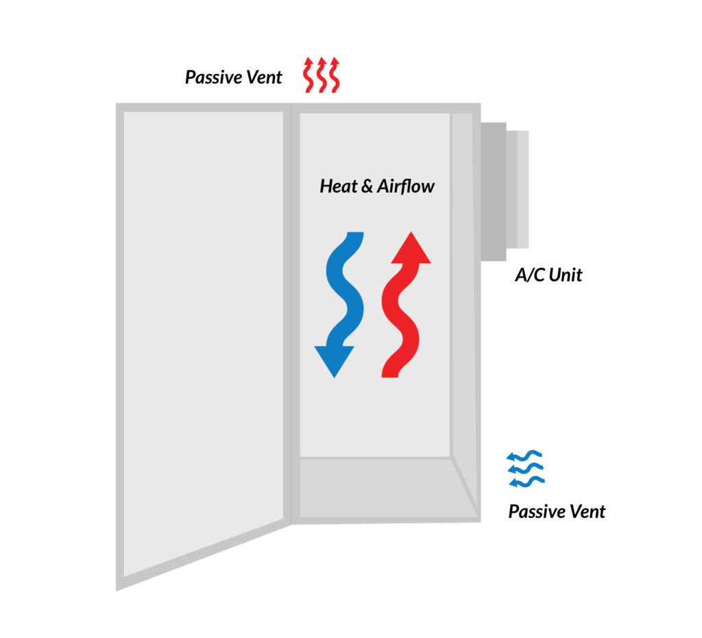
Natural Convection
This is the most basic form of airflow. When heat rises, cold air is pushed to the bottom of a space. If convection isn’t properly addressed, a hot spot will form at the top of the enclosure.
Natural convection cooling is adequate for most applications that generate mild heat. But, an easy solution is passive ventilation, or louvres.
Louvres are open, unfiltered vents positioned to allow ambient air to be drawn into the enclosure through openings positioned low on the enclosure surface, and to exit through similar openings positioned high on the same surface. They’re also a popular option because they provide some protection against dust entry.
Forced Convection
Using the same principles as described above with natural convection, forced convection adds a fan, blower or compressed air to force the warmed air through the enclosure and out through the upper vent.
Axial fans are typically capable of delivering high volumes of air at medium to low pressure
Blowers, or centrifugal fans, change the direction of the air, typically 90 degrees, and push the air out through a ducted system. They offer higher pressure with a lower flow.
Fan trays are used to direct airflow to hot spots when there is restricted airflow due to servers, drawers or shelves. It’s basically a chassis with a fan cooling module that can be mounted directly below the sensitive equipment or a hot spot. At A&J we’ve created a separate sub assembly that support fans with related parts such as EMI and dust filters.
Air Conditioning
For critical and thermally sensitive applications, or sealed cabinets, air conditioners provide the greatest capacity to transfer heat. Most air-conditioned cabinets are sealed with only inside air circulated inside to prevent moist air from entering and causing condensation.
Basic Airflow Calculations
For For ∆T in degrees F: Airflow (ft3/min) = BTU/hr / (1.08 × ∆ΤF) = (3170 × kW) / ∆ΤF
For ∆T in degrees C: Airflow (ft3/min) = BTU/hr / (1.95 × ∆ΤC) = (1760 × kW) / ∆Τc
Typical values for ∆Τ are 10C and 18F. Add 25 percent for a safety margin (12.5C and 23F). Note that ∆Τ represents the temperature rise over ambient air temperature. If ambient is too high, it may be difficult or impossible to maintain a safe operating temperature without air conditioning.
Components with significant heat generation should be given extra space to exhaust the heat and allow for proper airflow around them. Place these items closer to the intake of the AC, if using.
Components that run cooler can be stacked closer together. Airlfow is less of a requirement with these pieces because they have minimal effect on overall heat within the enclosure.
There should be clearance to walls and doors; keeping the hotter components away from walls of the enclosure allows for better circulation of air within the space.
When a component has an active airflow through internal fans, directing the airflow towards the AC intakes will help the cooler to perform more efficiently. It is more beneficial to get the hot air from the equipment into the AC, than it is to get the cold from the AC to the equipment.
Special consideration should be made when components have internal fans mounted on its front panel. It is common to recess the front retma bars and/or specify a deeper door to ensure proper airflow facing the front of the rack.
Thermal Management Solutions to Consider
When planning your next project design, consider these three solutions:
Fans – one of the oldest solutions to help boost natural ventilation. An air filter should always be used to minimize dust and debris, but ensure that the free-airflow rate (CFM) is three times grater than the calculated flow rate.
Enclosure air conditioners – a viable option when the capacity requires over 1000 BTUH and especially beneficial if you’re operating in an environment that has wide temperature fluctuations.
Air to air heat exchangers – a low-energy and low-maintenance solution that uses a heat pipe to absorb the heat inside the enclosure and transfer it to the outside via a phase-changing liquid under vacuum. However, it requires that the ambient air outside the enclosure be lower than the air inside.
We’re committed to helping you get the most out of our enclosure cooling options
Discuss your specific requirements with our engineers to get the most cost effective solution for your cooling needs. Get more information about configuration and placement from our experts.
Posted by A & J Manufacturing on | Comments Off on EMI / RFI shielding: what it does and why it’s important
EMI, orelectromagnetic interference, and RFI, or radio-frequency interference, are both types of electromagnetic radiation. EMI is emitted by electronic devices and can interfere with the proper functioning of other electronic devices, while RFI is emitted by radio waves and can interfere with radio signals.
EMI and RFI shielding is a process of enclosing electronic devices in a material that absorbs or reflects electromagnetic radiation to protect the devices from interference.
It can prevent everything from minor crackling during broadcasting to deadly malfunctions in aircraft safety equipment. If left unmitigated, it can disrupt the essential functions of electronic devices or erase or damage data. Even satellites in space need to be shielded from EMI/FRI to function properly.
Common sources of EMI/RFI include cell phones, microwaves, power lines and computer circuits. There are all natural causes of these signals such as auroras, solar flares or lightning.
What is EMI / RFI shielding, and what does it do?
EMI/RFI shielding is a process or material used to protect electronic equipment from EMI and RFI. EMI/RFI shielding can protect against various sources, including radio waves, microwaves, and electrical currents.
EMI/RFI shielding creates a barrier between the electronic equipment and the source of interference. This barrier can be made with a variety of materials.
Materials used for EMI/RFI shielding
For EMI/RFI shielding, avariety of materials can be employed. The following are the most frequent materials:
Metals
Conductive plastics
Carbon-loaded plastics
Conductive coatings
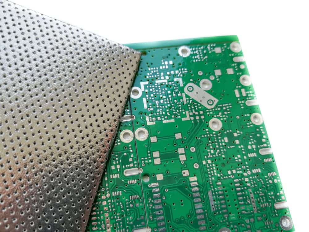
Metal mesh
Metals are the most common material used for EMI/RFI shielding. They are effective because they reflect and absorb electromagnetic radiation.
Importance of EMI / RFI shielding in electronic devices
EMI/RFI shielding is essential in electronic devices because it can help to reduce or eliminate interference that can lead to errors, data loss, and equipment damage. Shielding can also help improve electronic device performance by reducing interference from outside sources.
EMI/RFI shielding creates a barrier between the electronic equipment and the source of interference. This barrier is produced with various materials, including metals, conductive plastics, and special coatings.
How to choose the right EMI / RFI shielding for your needs
When choosing EMI/RFI shielding for your electronic devices, it is vital to consider the type of interference you are trying to protect against, the level of protection you need, and the environment in which the electronic devices will be used.
Some EMI/RFI shielding types, such as metal shielding, can block a wide range of frequencies. However, metal shielding can also block signals you may want to receive, such as radio waves. In addition, metal shielding can interfere with the proper functioning of some electronic devices.
Other EMI/RFI shielding types, such as conductive plastics and special coatings, can be customized to block specific frequencies while allowing others to pass through. These materials can also be used in various environments, including wet or humid ones.
Common applications for EMI / RFI shielding
EMI/RFI shielding is used in a variety of industries, including:
Automotive
Aerospace
Telecommunications
Medical
Mass transit systems
Navigation and vehicular control systems
Keep your electronics interference-free
If you’re looking for ways to protect your electronic devices from interference, look no further than EMI and RFI shielding. Enclosed devices in a material designed to absorb or reflect electromagnetic radiation to keep them functioning correctly. At A&J we use a .140 diameter tubular gasket (210-1130) that is added to the extrusion grooves and consists of a silicone inner core that is plated with silver / aluminum for the seams between the frame members that are joined together.
Our enclosures are attenuated to 60 DB from 150 Hz to 1 million Hz and 40 DB from 1-2 million Hz in accordance with MIL-STD-461G for EMI/RFI shielding. Our team of professionals can help you determine the type of shielding your rack or enclosure needs and install it quickly and efficiently.Contact us today!
Posted by A & J Manufacturing on | Comments Off on Rack Mounting Options for your Electronic Equipment
A rack mount is a description of a hardware device capable of being mounted in an equipment rack. All types of electronics and computing devices come in rack-mounted packages including servers, test instruments, telecommunications components, which are bolted to the side frames of the rack. Note: shelves are available for equipment that is not rack mounted.
Measuring cabinet dimensions, specifically depth
Before ultimately choosing a rack mounting option, let’s first review how to properly measure your rack space. As a reminder, cabinets or enclosures are traditionally referred to by their external dimensions. But in most cases, the rack depth is 4 to 6 inches less than the external cabinet depth.
To measure the rack depth, measure the distance between the forward-most part of the front rail to the rear-most point of the rear rail. A&J typically recommends 34 in. (86.36 cm) or greater cabinets for use with equipment that have an average depth of 28 in. (71.12 cm). The 6 inches (15.24 cm) at the back between the equipment and the back door or panel allows for cable management, airflow and maintenance access.
Equipment mounting options
Originally mounting holes were tapped with a particular screw thread, but has since become problematic where equipment is frequently changed because the threads are easily damaged or the mounting screws can break off. Both problems render the mounting hole unusable.
Tapped-holes were then replaced by clearance-hole racks. Holes are large enough to permit a bolt without binding and fastened in place using cage nuts.
The third innovation has been square-hole racks. These racks allow boltless mounting where the weight of the equipment and small retention clips are all that is necessary to hold equipment in place.
The structural support
A key structural weakness of front-mounted support is the bending stress placed on the both the rack itself and the mounting brackets of the equipment. Our A&J racks can incorporate front and rear rails that may be moved forwards and backwards that allows equipment to be supported by four posts, but also easily installed and/or removed.
Our standard AJR 150 Series 4-post racks are 22.31″ (566.6 mm) wide with three depths: 26″, 30″, 36″ (660.4 mm to 914.4 mm). The extra width and depth enables cabling to be routed with ease and deeper equipment to be installed. It can also accommodate “Zero-U” accessories such as PDUs and vertical cable managers in the space between the rear rails and the side of the enclosure.
Rails (slides)
Often used for heavy equipment that requires regular servicing, a pair of rails can be mounted directly onto the rack which allows the component to slide into the rack along the rails. The equipment can then be bolted to the rack (as described above) or the rails may also be able to fully support the equipment in a position where it has been slid clear of the rack. Consider purchasing a cable management arm, which folds the cables attached to the server or component and allows them to expand neatly when the rail is slid out, without being disconnected.
Tools required
You will need some of the following tools to rackmount your equipment:
Philips No. 1, No. 2, and No. 3 screwdrivers
Flat-blade No. 1 and No. 2 screwdrivers
Allen and adjustable wrenches
Needlenose pliers
Level
Electrostatic discharge (ESD) wrist strap
ESD mat
Rack Mounting Tips & Guidelines
Install the heaviest equipment and storage devices in the lowest position in the rack to prevent the rack from becoming too-heavy and prone to tipping over.
Install any remaining equipment from the lowest system upward into the rack.
For applications that require high-density cabling, you may need 1U of horizontal cable management for every 1U of patch panels or switches.
Ensure the rack is properly secured to the floor or ceiling and level before installing any components.
Posted by A & J Manufacturing on | Comments Off on Benefits of a Modular Enclosure
As the Industrial Internet of Things (IIoT) continues to transform industrial engineering, system designers and engineers are under growing pressure to deliver solutions that are faster, more adaptable, and future-ready. In this fast-moving landscape, it pays to design with versatility and modularity in mind.
Yet despite the growing adoption of modular enclosures, several misconceptions still exist about what truly defines one—and how they differ from other enclosure types. A fully realized modular enclosure empowers organizations to respond more efficiently to evolving market demands, supply chain variability, and high-mix, low-volume production environments.
Let’s clarify the terms often used interchangeably—and incorrectly.
What a Modular Enclosure Is and Isn’t
❌ Unibody Enclosure
A unibody enclosure is typically constructed from a single welded frame made of heavy-gauge sheet metal. While extremely durable, this rigid, all-in-one design limits flexibility and can complicate access during maintenance or system upgrades. Modifications often require costly cutting, welding, or complete replacement.
⚠️ Modified Enclosure
A modified enclosure usually refers to a standard enclosure that’s been customized with drilled holes, knockouts, or tapped panels to fit specific components. While this may offer a degree of flexibility, it lacks the structural modularity needed for efficient reconfiguration or scalability over time.
✅ Modular Enclosure
A true modular enclosure is built on a frame-based architecture with standardized mounting rails, interchangeable panels, and accessory options that can be easily rearranged without additional fabrication. This design supports reusable components, easy reconfiguration, and rapid deployment—saving both time and cost as needs evolve.
Key Benefits of a Modular Enclosure
Infinite configuration possibilities – Modular frames use pre-punched, standardized hole patterns (such as EIA-310 units) that accept a wide range of components without additional drilling. Cabinets can also be bayed side-by-side to create custom enclosures of virtually any size or layout.
Faster mounting & installation – With rails and removable side, front, and rear access points, panels can be mounted without tipping the enclosure or using heavy machinery like cranes. This reduces labor and installation time while improving safety and ergonomics.
Built to last – Thanks to vertical framing and robust material construction, modular enclosures retain their protective strength without sacrificing flexibility. Many designs are compliant with MIL-S-901D, NEMA, or other industry standards—ensuring suitability in rugged, mission-critical applications.
Flexibility – Designers, integrators, and end-users can tailor modular enclosures for simple or complex builds. Configurations can accommodate airflow, thermal management, cabling, and maintenance access without any structural changes or downtime.
Maximizes floor space – Floor space is at a premium in industrial and military environments. Modular enclosures allow for optimized layouts, dual-layer mounting (internal and external), and precise footprint customization—all while maintaining internal accessibility and serviceability.
Core Elements of a Modular Enclosure
To function effectively in demanding environments, a modular enclosure should include the following:
Device Protection – Like unibody designs, modular enclosures protect sensitive electronics from environmental hazards like dust, moisture, tampering, and corrosion. Look for models tested and certified to meet standards such as NEMA, IP, and MIL-S-901D. Also consider local environmental factors (e.g., salt spray, humidity, UV) when selecting enclosure materials and finishes.
Compartmentalization – Modular designs allow for thermal zoning and equipment segregation within a single frame. This supports integrated climate control (e.g., fans, heat exchangers, A/C) without needing multiple cabinets or separate cooling systems.
Ease of modification – As production sequences or operational needs change, modular enclosures make it easy to scale up, scale down, or reconfigure. Swapping out doors, panels, or accessories doesn’t require structural changes, welding, or re-certification.
Mounting panels – The mounting panel is the heart of most enclosures—and in modular builds, it can slide in from the front, side, or rear. No need to tip the unit or lift with cranes. This streamlines assembly and maintenance dramatically.
Availability of sizes and types – Modular enclosures come in standard sizes but can also be configured with full/half doors, multiple mounting panels, and front/rear/side cable entry to fit specific applications.
In today’s industrial and defense manufacturing environments, a modular enclosure isn’t just a convenience—it’s a competitive advantage. By offering greater flexibility, easier integration, and future-proof scalability, modular systems help organizations adapt faster, reduce downtime, and maximize ROI.
If your current enclosure strategy still relies on rigid or one-off solutions, it may be time to rethink what “modular” really means.